图1
PCR(聚合酶链式反应)是利用DNA在体外摄氏95°高温时变性会变成单链,低温(经常是60°C左右)时引物与单链按碱基互补配对的原则结合,再调温度至DNA聚合酶最适反应温度(72°C左右),DNA聚合酶沿着磷酸到五碳糖(5'-3')的方向合成互补链。基于聚合酶制造的PCR仪实际就是一个温控设备,能在变性温度,复性温度,延伸温度之间很好地进行控制。而简易灯泡PCR仪便是用灯泡来加热,用电脑的风扇来冷却,达到控制温度的目的。温度按照PCR反应要求循环30次左右,达到PCR反应要求。在家庭中,PCR试验还能测试食品安全性,监控水质
关键词:PCR 温控设备 升温 冷却
正文
引言
聚合酶链式反应是一种用于放大扩增特定的DNA片段的分子生物技术,它可看作是生物体外的特殊DNA复制,PCR的最大特点,是能将微量的DNA大幅增加。因此,无论是化石中的古生物、历史人物的残骸,还是几十年前凶杀案中凶手所遗留的毛发、皮肤或血液,只要能分离出一丁点的DNA,就能用PCR加以放大,进行比对。这也是“微量证据”的威力之所在。由1983年美国Mullis首先提出设想,1985年由其发明了聚合酶链反应,即简易DNA扩增法,意味着PCR技术的真正诞生。到如今2013年,PCR已发展到第三代技术。1973 年,台湾科学家钱嘉韵,发现了稳定的Taq DNA聚合酶,为PCR技术发展也做出了基础性贡献。
但PCR仪价格普遍较高,一般都要上万元起步,而简易灯泡PCR仪利用了普通的灯泡和多余的电脑风扇,材料简便,成本低廉。它使用Arduino软件和单片机连接来控制灯泡加热和风扇散热,可以达到控制温度的效果。
研究过程
1.用Arduino做简单温度计
D18B20温度传感器,这款传感器能够测量0-100摄氏度的温度,并以电压的数值输出。从0度开始温度每升高1度输出电压就会提高10mv,这样我们就能够使用模拟口检测传感器的电压,进过简单计算得到当前的温度数值。
程序代码:
#include
#include
// Data wire is plugged into pin 2 on the Arduino
#define ONE_WIRE_BUS 2
// Setup a oneWire instance to communicate with any OneWire devices
// (not just Maxim/Dallas temperature ICs)
OneWire oneWire(ONE_WIRE_BUS);
// Pass our oneWire reference to Dallas Temperature.
DallasTemperature sensors(&oneWire);
void setup(void)
{
// start serial port
Serial.begin(9600);
Serial.println("Dallas Temperature IC Control Library Demo");
// Start up the library
sensors.begin();
}
void loop(void)
{
// call sensors.requestTemperatures() to issue a global temperature
// request to all devices on the bus
Serial.print(" Requesting temperatures...");
sensors.requestTemperatures(); // Send the command to get temperatures
Serial.println("DONE");
Serial.print("Temperature is: ");
Serial.print(sensors.getTempCByIndex(0)); // Why "byIndex"?
// You can have more than one IC on the same bus.
// 0 refers to the first IC on the wire
delay(1000);
}
设想利用这款温度传感器,来测量仪器内试剂温度,并通过监视器进行监视,获得实时温度大小,用以观察仪器内试剂温度。
2.继电器控制灯泡
(继电器,是一种电子控制器件,通常应用于自动控制电路中,它实际上是用较小的电流去控制较大电流的一种“自动开关”。故在电路中起着自动调节、安全保护、转换电路等作用。)
由于灯泡运行在220伏交流电,所以 Arduino需要控制一个继电器,打开和关闭灯电路。而单片机工作在5V,电灯是220V,因此需要由单片机控制一个继电器,通过控制这个继电器充当电灯的开关。
继电器的输出回路一般有三个触点,中间的触点是动触点(公共端),其它两个触点是静触点。
输入回路不通电时,动触点(公共端)总是和一个静触点断开(称为常开),与另一个静触点闭合(称为常闭)
为了通过灯泡的闪烁发热来达到使温度能够控制在一定范围内效果,加入以下代码。
程序代码:
int a,val; //定义变量
float temperature; //定义浮点型变量,用于存放转换后的温度
int B=3975; //热敏电阻的基础参考值B
float resistance;
void setup()
{
myservo.attach(4); //定义舵机驱动端口
}
void loop()
{
a=analogRead(0); //读取温度传感器的模拟值
resistance=(float)(1023-a)*10000/a; //计算出传感器的电阻值
temperature=1/(log(resistance/10000)/B+1/298.15)-273.15;//将电阻值转换成温度值
delay(500); //延时500毫秒
val=map(temperature,0,50,0,180); //将转换的温度值映射到舵机的角度值
}
3.风扇
加热10秒,温度升到30度,风扇吹30秒,温度降到26度,实验结果如下:
程序代码:
#include
#include
// Data wire is plugged into pin 2 on the Arduino
#define ONE_WIRE_BUS 2
// Setup a oneWire instance to communicate with any OneWire devices
// (not just Maxim/Dallas temperature ICs)
OneWire oneWire(ONE_WIRE_BUS);
// Pass our oneWire reference to Dallas Temperature.
DallasTemperature sensors(&oneWire);
void setup(void)
{ // start serial port
Serial.begin(9600);
Serial.println("Dallas Temperature IC Control Library Demo");
pinMode(13, OUTPUT);
pinMode(7, OUTPUT);
// Start up the library
sensors.begin();
}
void loop(void)
{
// call sensors.requestTemperatures() to issue a global temperature
// request to all devices on the bus
Serial.print(" Requesting temperatures...");
sensors.requestTemperatures(); // Send the command to get temperatures
Serial.println("DONE");
Serial.print("Temperature is: ");
Serial.print(sensors.getTempCByIndex(0)); // Why "byIndex"?
// You can have more than one IC on the same bus.
// 0 refers to the first IC on the wire
delay(1000);
digitalWrite(13, HIGH); // turn the LED on (HIGH is the voltage level)
delay(20000); // wait for a second
digitalWrite(13, LOW); // turn the LED off by making the voltage LOW
delay(200); // wait for a second
digitalWrite(7, HIGH); // turn the LED on (HIGH is the voltage level)
delay(60000); // wait for a second
digitalWrite(7, LOW); // turn the LED off by making the voltage LOW
delay(200); // wait for a second
}
4.总体连接
经过实验,从灯泡开始加热到整体温度达到90摄氏度需要大约60秒,接通风扇开始冷却恢复至温度30摄氏度大约需要90秒。
结论
研究发现
在这一次研究中,我们使用Arduino软件与单片机连接来控制灯泡发光加热和风扇转动降温,发现传感器实际应用效果非常棒。在实验过程中,我们也发现了自己在程序编码上的一些不足,通过查找资料和请教老师,我们最终克服了这些困难,锻炼提高了自己的能力。
参考文献
[1]李钧敏, 分子生物学实验,浙江大学出版社,2010.6
[2]王立铭,上帝的手术刀-基因编辑简史,浙江人民出版社,2017.5
[3]王月姣,朱家驹 固态继电器在单片机测控系统中的应用。中南民族大学学报 2005
图1
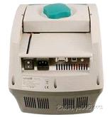
图2

图3
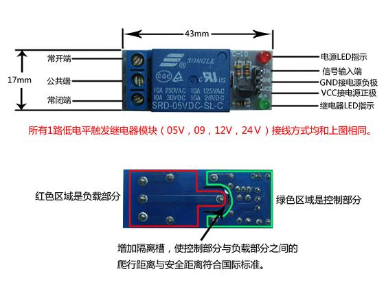
图4

图5
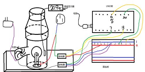
图6
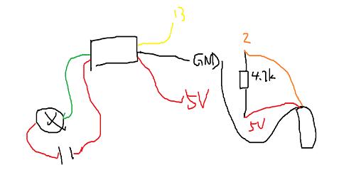
图7
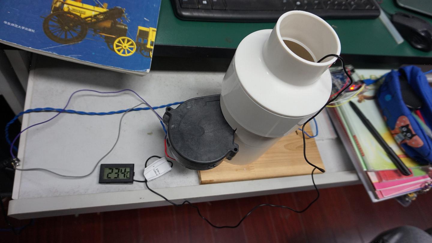
图8
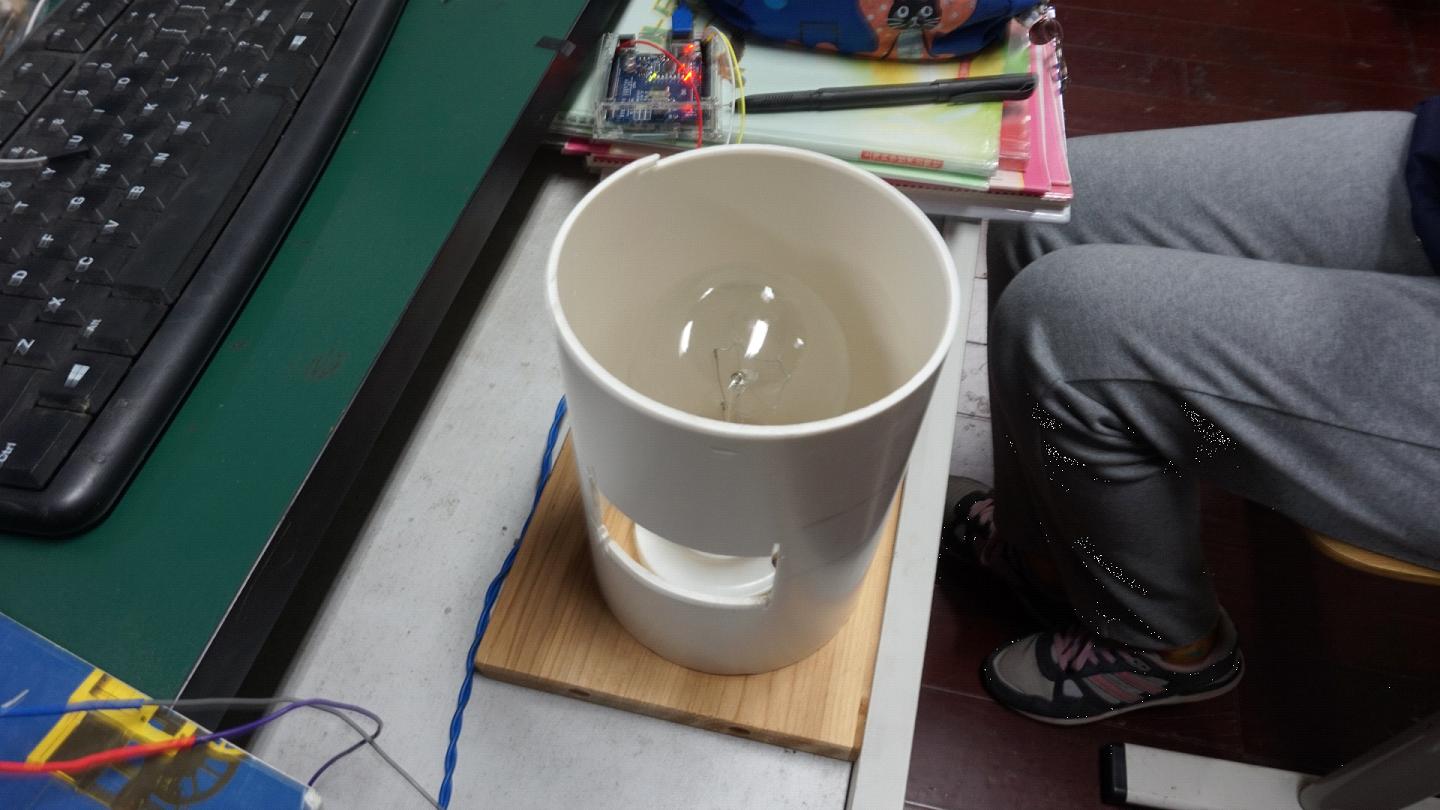
图9
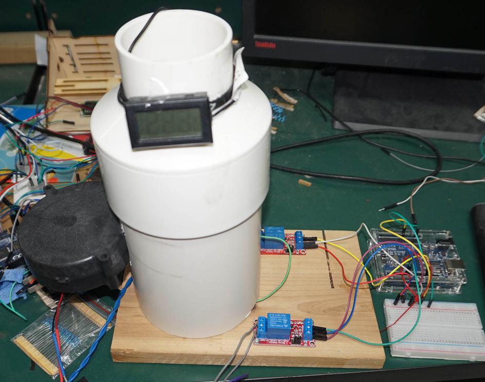
图10
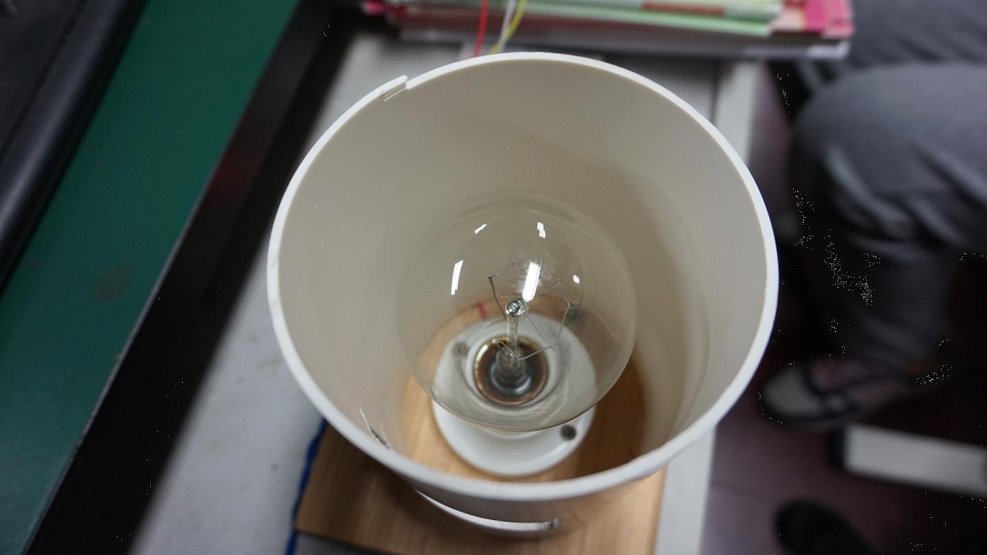
图11